Project: Inexpensive Firearm Accelerometer
Measure recoil, flinching, and more for under $50
You may have already read about this little gizmo from my previous article, where I used it to measure the relationship between Recoil and Muzzle Velocity. Of all the feedback I received, the accelerometer definitely generated the most interest.
What you may not know is that it wasn't the first experiment I had intended to use it on. My original plan was to correlate rifle movement to my 600 yard scores. I wanted to detect if I was flinching or jerking the trigger, resulting in a hit in the 9-ring (or worse).
In this article, I've provided more detail about how I built it, how it works, and how I'd like to improve it.
Update: I've written another article with an update on the incredible progress that's been made to this project. Most notably, it's nearly six times faster!
In a hurry? You can find the code and instructions to build your own over on GitHub.
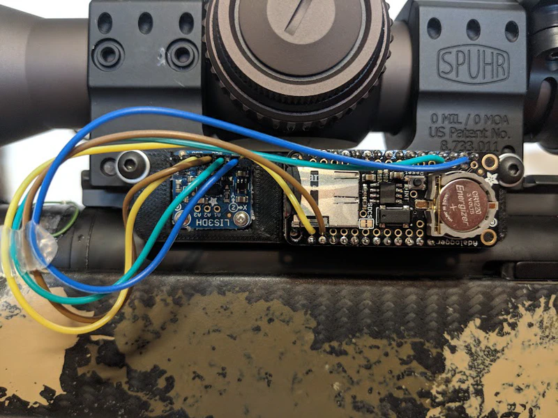
My homebrew 3-Axis accelerometer attached to a Spuhr mount.
Table of Contents
Existing Solutions
Before starting a project, it's a good idea to look around at how others have solved the same problem. Don't reinvent the wheel, as the saying goes. Admittedly, I only did a cursory glance at what was out there. Knowing that I would likely be frustrated by proprietary software that I couldn't tweak to my own needs, and because it only cost $5, I ordered a 3-axis sensor without hesitation.
Regardless, here's a brief overview of what you might find online:
A YouTube video from 2012 briefly demonstrated the fundamental concept, as well as some of the most extreme chicken-wing stance I've seen in a while. It appears to be a commercial product, but no data or details were provided beyond screenshots within the video itself.
The Slam Stick is a commercial accelerometer from Mide Technology. It comes in a small wireless package and boasts sample rates from 3.2kHz up to 20kHz, which is pretty appealing. The price range of $700-$3250, less so. While it appears to be a general-purpose solution, the company did write a blog post about a firearms use case.
Cal Zant from PrecisionRifleBlog.com built a more complicated rig for about $1,500 to measure perceived recoil. His system was capable of an impressive 48kHz sample rate, but it's worth clarifying that it measures pressure (force) in a single axis and not acceleration.
Finally, the MantisX is another compact wireless unit that's specifically designed for firearms, controlled by a smart phone app, and mounts on picatinny rails. At the time of writing, it retails for around $150. I couldn't find any specifics about its sample rate, or whether or not it provides the raw data, though it does appear to have positive reviews.
Project Goals
The rough idea was to measure the precise movements of my rifle just before, during, and just after each shot. I wanted to detect lateral movement that you would expect from flinching or bad trigger pulls (jerking, overtravel, sneezing, etc).
Here are a few maxims I knew would be true of this project:
- Simple is better than complex
- Fast is better than slow
- Small is better than large
That said, you have to start somewhere. The first prototypes rarely resemble the finished product. To maintain focus, I set a few rules for myself:
- Use off-the-shelf components
To get to a working prototype, I wanted to avoid the overhead of circuit board design, surface mount components, reflowing, and soldering as much as possible. Companies like Adafruit, SparkFun, DigiKey, Mouser, eBay, and Amazon make it really convenient to order sensors and components. The breakout board format uses jumper wires and protocols like I2C and SPI to create a plug-and-play experience that vastly speeds up development. - Stick to what you know
Few things can grind a project to a halt quicker than introducing new tools. To keep things moving fast, I stayed inside my comfort zone for writing software. I used the standard Arduino IDE and programming language for the Arduino Uno, and a combination of Python and Unix shell scripts on the Raspberry Pi.
First Attempt
The accelerometer sensor I used is capable of a 5kHz sample rate. This was both the fastest and most affordable accelerometer I could find. The sensor would send information with the I2C protocol to the Arduino. The Arduino would convert this raw data into a CSV-formatted stream over USB. The Raspberry Pi would read the stream and write it to disk with simple Unix pipes.
Components
Note: There are excellent guides available for this board from Adafruit and SparkFun which cover everything you need to know about hooking up the wires to programming. I highly recommend reading those if you plan on building your own.
Problems
While this first prototype was functional, this setup benefited from very simple software and suffered from complicated hardware.
- There were a bunch of cables that had to be connected to the right ports in the right order.
- The Arduino and Pi were both way too cumbersome.
- The data couldn't be read directly off of the SD card.
- A USB battery pack was needed to power everything.
- Two devices had to be updated to change the software.
- Mounting with hot glue was extremely low-tech and difficult to remove.
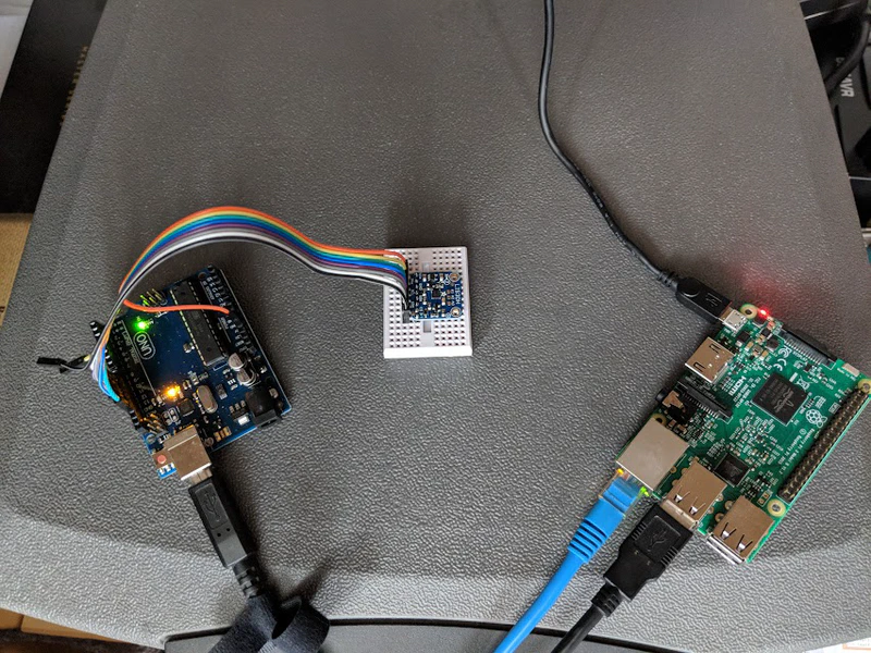
Initial component connection and prototyping phase.
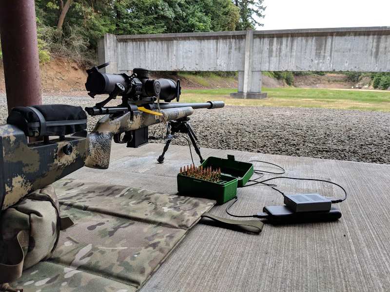
The earliest prototype used an Arduino Uno, Raspberry Pi, and large USB battery.
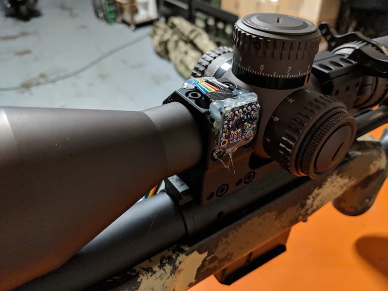
The first attempts at mounting were crude, with heavy applications of hot glue.
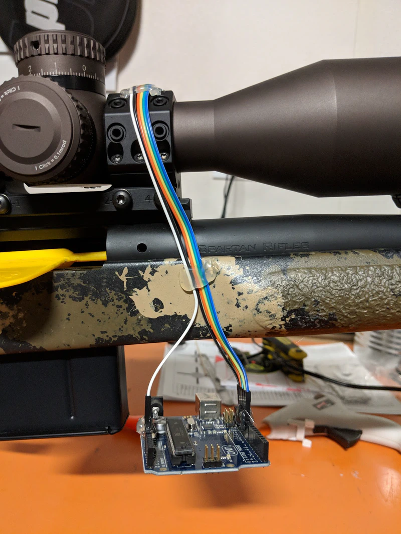
On the first prototype, an Arduino Uno was left dangling from the rifle.
Second Attempt
Two things had to change immediately:
- It had to be a single, compact unit
Two devices and all of the wires turned into a real pain whenever I had to extract the data or make changes to the software. Not to mention the hassle of dealing with all of that stuff at the range. I switched to the Adafruit Feather M0 board – a compact Arduino supported by snap-on accessories (called shields). The Raspberry Pi was only used to write the data to disk. It was replaced by the Adalogger Featherwing, with RTC and micro-SD card. - The mount had to be removable
Peeling off hot glue every time I wanted to update the software or clean the rifle wasn't going to cut it. I'm fortunate (and nerdy) enough to have a 3d-printer in my office. I took some dimensions of the components and the Spuhr mount, then used Fusion360 to design a frame. Some really tiny screws are used to retain the breadboards. A better design and higher resolution printer may allow for snap-assembly.
Components
- Adafruit LIS3DH Triple-Axis Accelerometer
- Adafruit Feather M0 Bluefruit LE Bluetooth isn't required for this project, so you could consider a less expensive option, like one with a built-in microSD slot.
- Adalogger FeatherWing - RTC + SD
- 3.7V 500maH LiPo Battery
- 3d-printed mount
Before the FeatherWing arrived, I went through a few designs of the 3D mount. I still had to use the Rasberry Pi, but at least I could easily remove the sensor from the rifle and didn't have a huge Arduino hanging off by some jumper wires.
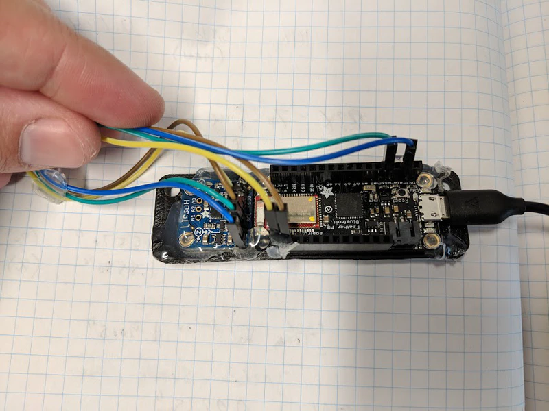
The first 3d-printed frame to hold the Adafruit Feather and accelerometer sensor.
Data Processing and Results
Let's take a closer look at the information this unit provides. The Recoil vs Muzzle Velocity experiment fired 25 rounds in 30 minutes and createad a 5.6MB CSV file, which is fairly large. It was recording a sample roughly every 6 milliseconds, or close to 140 samples per second. In addition to three axis of acceleration, it's also storing timestamps and battery voltage.
The following table shows a small sample of raw data for one fired round. Those who are interested can download the complete dataset.
| timestamp | accel x | accel y | accel z | accel unit | sensor range | millis | micros | voltage |
|---|---|---|---|---|---|---|---|---|
| 1535375188 | 0.54 | 9.48 | -0.29 | m/s^2 | 4 | 445 | 446063 | 4.16 |
| 1535375188 | 0.63 | 9.39 | -0.10 | m/s^2 | 4 | 454 | 454394 | 4.14 |
| 1535375188 | 0.67 | 9.39 | -0.40 | m/s^2 | 4 | 460 | 460487 | 4.16 |
| 1535375188 | 0.36 | 9.60 | -0.38 | m/s^2 | 4 | 466 | 466572 | 4.16 |
| 1535375188 | 0.44 | 9.45 | -0.33 | m/s^2 | 4 | 472 | 472649 | 4.15 |
| 1535375188 | 0.54 | 9.39 | -0.31 | m/s^2 | 4 | 478 | 478727 | 4.15 |
| 1535375188 | 0.69 | 9.45 | -0.36 | m/s^2 | 4 | 484 | 484815 | 4.15 |
| 1535375188 | 0.63 | 9.41 | -0.21 | m/s^2 | 4 | 490 | 490910 | 4.15 |
| 1535375188 | 0.57 | 9.52 | -0.21 | m/s^2 | 4 | 525 | 525100 | 4.16 |
| 1535375188 | 0.71 | 9.41 | -0.02 | m/s^2 | 4 | 531 | 531155 | 4.15 |
| 1535375188 | 0.69 | 9.46 | -0.27 | m/s^2 | 4 | 537 | 537241 | 4.16 |
| 1535375188 | 0.57 | 9.37 | -0.11 | m/s^2 | 4 | 543 | 543330 | 4.16 |
| 1535375188 | 0.52 | 9.39 | -0.13 | m/s^2 | 4 | 549 | 549408 | 4.16 |
| 1535375188 | 0.56 | 9.43 | -0.15 | m/s^2 | 4 | 555 | 555486 | 4.16 |
| 1535375188 | 0.48 | 9.54 | -0.25 | m/s^2 | 4 | 561 | 561563 | 4.15 |
| 1535375188 | 0.54 | 9.43 | -0.21 | m/s^2 | 4 | 567 | 567650 | 4.16 |
| 1535375188 | 0.48 | 9.41 | -0.06 | m/s^2 | 4 | 576 | 576852 | 4.16 |
| 1535375188 | 0.50 | 9.45 | -0.19 | m/s^2 | 4 | 582 | 582931 | 4.16 |
| 1535375188 | 0.52 | 9.39 | 0.13 | m/s^2 | 4 | 588 | 589011 | 4.15 |
| 1535375188 | 0.56 | 9.41 | 0.48 | m/s^2 | 4 | 595 | 595087 | 4.16 |
| 1535375188 | 0.71 | 9.33 | -0.04 | m/s^2 | 4 | 610 | 610660 | 4.16 |
| 1535375188 | 0.65 | 9.45 | -0.11 | m/s^2 | 4 | 618 | 619010 | 4.15 |
| 1535375188 | 0.52 | 9.33 | -0.46 | m/s^2 | 4 | 625 | 625097 | 4.15 |
| 1535375188 | 0.48 | 9.46 | 0.00 | m/s^2 | 4 | 630 | 631039 | 4.15 |
| 1535375188 | 0.52 | 9.43 | -0.11 | m/s^2 | 4 | 637 | 637126 | 4.15 |
Charts
Since tabluar data tends to be rather boring, let's visualize the data to get a better understanding of what it's trying to tell us. I used Pandas to analyze the data in the Python programming language and Plotly to generate the graphs.
Note: The sensor provides acceleration in metric (m/s²), but I converted to imperial units (ft/s²) for the charts below.
The following charts are from the same dataset and visualize all three axes. I opted for images instead of an interactive chart for two reasons:
- To walk you through and zoom in on one shot
- Interactive charts would be too slow on mobile devices
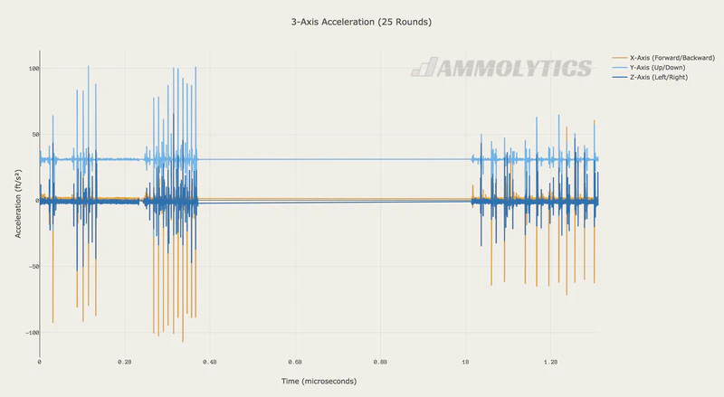
All three axes plotted. The Y-Axis is inline with Earth's gravity, resulting in higher values.
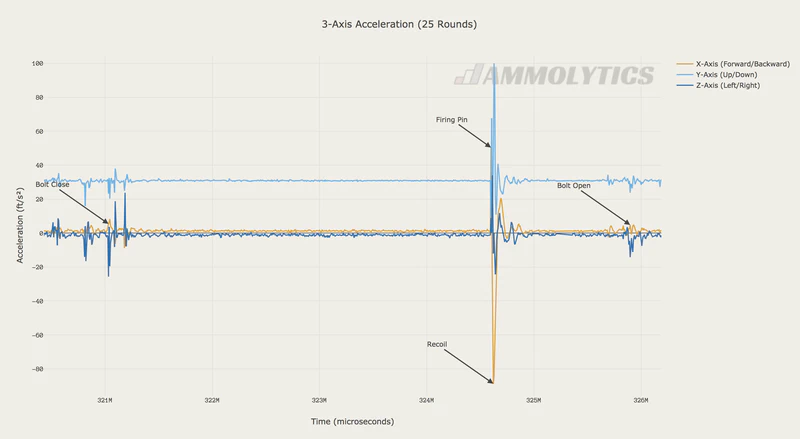
Zooming in on single round – loaded, fired, and unloaded
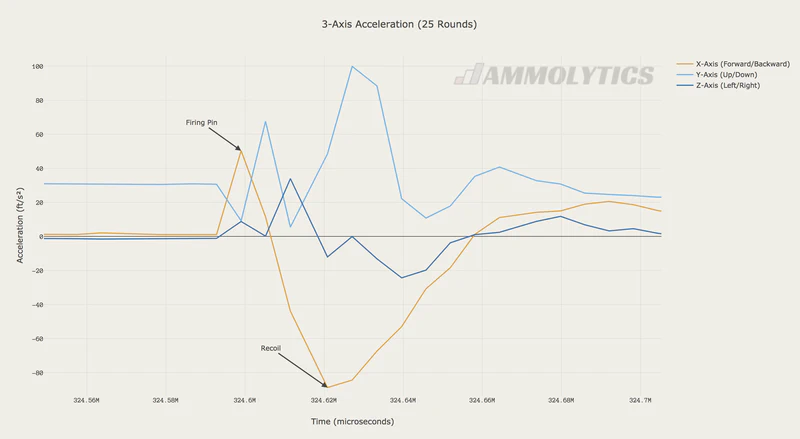
Zooming in again when the round was fired.
Rewinding to my original goal, I wanted to see if I could detect any movement which might lead to inaccuracies on target, such as sloppy trigger pulls or flinching. Looking thorugh this dataset, I found at least one instance, as you can see below. Unfortunately, I was shooting at a steel target so I don't have any evidence to show what effect this had downrange.
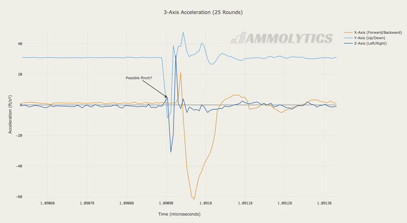
Did I flinch or jerk the trigger? Disruption on the Z-Axis (Left/Right) before breaking a shot.
Lessons Learned
Here are a few takeaways from my experience working with this sensor and Arduino-based microprocessors.
- Accelerometer orientation is critical
As long as you're on planet Earth, the sensor will always detect gravity. To maintain discrete acceleration levels for each axis, the sensor must be mounted 90° towards the ground. Otherwise you'll end up with noise from the acceleration from gravity on two axis that has to be sorted out later. Fortunately, mounting scopes on rifles have the same requirement, which makes those mounts an ideal surface for this type of sensor. - Arduino doesn't know what time it is
Without accessories, an Arduino has no way to keep track of the date or time of day. Instead, it counts up from the moment it was powered on in milliseconds and microseconds. This provides relative time, but I wanted wall-clock time. Adding a Real Time Clock (RTC) unit which uses a coin-cell battery to maintain power to the clock, allowed me to set the date/time that it could remember. - Performant Arduino code is an artform
Much of the software I wrote for this project was based off of the examples provided for the sensors. However, performance is a feature and not one that is important for tutorials. I had to do a bit more research to learn things like debug commands are really slow. I added a debug flag that gives me a speed boost when I run the unit in the field. - Writing data to disk is slow
Once I added the Adalogger FeatherWing, I could write the acceleration data directly to disk. Then my problem was, my Arduino had to write the acceleration data directly to disk. There's a significant delay when storing data, which means you're not collecting more data. Memory on the Arduino is limited, and it could be powered off at any time, so you have to write regularly. Writing the data during a shot was a huge risk, since that's when you really want to be collecting the most data. I had to use the sensor data to guess at "downtime" between shots, then write the data.
Future Improvements
Projects like this are never really finished. Hopefully this inspires others to build their own and to contribute so that it can improve for everyone. Here are a few ideas that stand out in my mind:
- Use faster sensors
The LIS3DH was the fastest and most affordable chip I could find at the time. If anyone knows of an inexpensive option capable of greater than 5kHz, let me know! - Add a position sensor
Accelerometers only sense motion. A position sensor can provide orientation and direction data, making it even more useful. The Adafruit 9-DOF IMU seems like a good option. - Drop unecessary data
High sample rates lead to a mountain of stored information, but not all of it is useful. This project would benefit from ignoring data between shots. One idea is to buffer everything and only write a couple of seconds worth before and after a shot is detected. - Separate output files
The code currently writes all data to a filename based on the current date. It'd be better to separate sessions into their own files. - Design an enclosure
The battery is still dangling and the boards are exposed. - Create more mounting options
Not everyone has a Spuhr mount, so adding options for picatinny, KeyMod, M-Lok, or ARCA would be a huge improvement. One suggestion I heard was to use this sensor to record barrel whip. I'm not entirely convinced it's fast enough, but I'd love to know if someone tries to do this! - Add a power switch
Connecting and disconnecting the battery isn't a great solution. It'd be nice to have a simple on/off switch to control the device.
Next Steps
- Share your builds
I'd love to see what you build and experiment with this concept! Share with me on Instagram or any other social media (links in the footer)! - Have questions or feedback?
You can discuss this project with me on Reddit. - Participate
You can create Pull Request over on GitHub if you'd like to help improve this project. I'll update this post periodically to credit anyone who makes major contributions. - Contribute
Ammolytics is a community-supported project to keep it free of ads and paid-promotions. Making purchases using the affiliate links on this site helps to fund future projects and experiments. You can also support Ammolytics on Patreon!
Special thanks
- My friend Andy, for reviewing this article and giving me some excellent feedback. (He's writing a new Unix shell called Oil!)
Before you go…
Thanks for taking the time to read this article! I enjoyed writing it and learned a lot in this process and I hope that you did too. If you have any feedback, you can email me directly if you don't prefer to use Reddit or other social media.
